Category Archives: Integratred Circuits

Diode Logic

It’s a fairly trivial task to use small signal diodes to form digital logic gates. Diodes are cheap and it can be very cost effective to use them in place of dual-in-line integrated circuits.

or-gate.
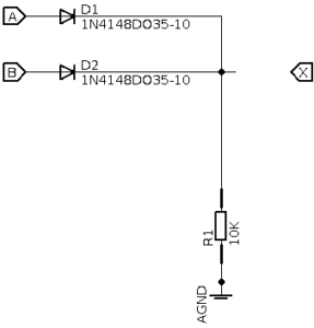


The output of the gate is connected via a tie-down resistor R1 to ground. This ensures that when no input signal is applied to input A or input B the output of the gate X remains low.

When either of the inputs become high the diode will conduct and a current will flow through the resistor to ground. There will be a voltage drop across the diode of approx 0.7V when it’s conducting so the voltage at point X will be Vin-0.7 so for a 5V input the output will be at 4.3volts which is sufficient to be defined as as a ‘high’ in logic terms.

The ‘gate’ in extensible so all you need to do is to add additional diodes to create more inputs.

and-gate.

The and gate is a simple modification of the or-gate logic. by connecting the resistor to a positive supply voltage and reverse biasing the diodes the circuit will now work as and and-gate
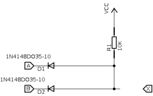
When both inputs are low points A and B are virtual grounds and the supply voltage is dropped across the resistor so point X is at zero.

Consider when A is high and B is low. D1 is now reversed biased no no current will flow through it, but it will flow through D2 and point X is at zero. The same argument holds when B is now high and A is low.

Now when A and B are both high both diodes are reversed biased and no current will flow through the circuit so the supply voltage will appear at output point X and the output of the circuit is high.


The NAND gate

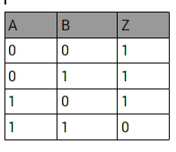
Digital logic ICs come in all types but to my mind the NAND gate is the most flexible device to have in your component box. NAND is a NOT AND gate and can be considered complementary to an AND gate meaning that the truth table is an AND gate in reverse. Why is that? Let’s take a look at the truth table for a common two input NAND gate


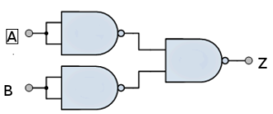
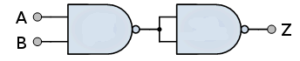
The NAND gate has beautiful flexibility because it can be configured to work as an inverter, AND gate, OR gate quite easily. For example want an AND gate? Then all you need to do is wire the output pin (Z) to both inputs of another NAND gate as shown below:


This reverses the truth table above and you have an an AND gate.

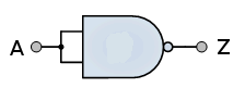
Want an inverter? then just connect both inputs A and B together and the output will be the inverse of the input signal as shown below:


This is really beautiful isn’t it? An OR gate is slightly more complicated and will require 3 NAND gates to accomplish our task.


Now isn’t that just beautiful pure logic? 🙂

The (ubiquitous) NE555 timer integrated circuit

The NE555 is an inexpensive timer IC that can be configured to run in monostable i.e a single stable state or in timer mode with the addition of a few passive components. It is very easy to use and configurable over numerous decades from a few miliseonds to several hours – although brief and long delays can be unreliable due to tolerances in the external passive components .

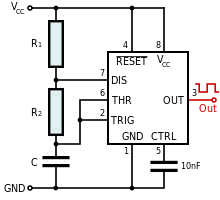
NE555 in the astable configuration


The circuit shown above shows the 555 configured as an astable multivibrator by selecting the values of R1, R2 and C1 the frequency of the oscillator can be configured.

The Clock out (pin3) frequency can be represented as follows:

Here’s a python script you can run to work out the component values. An approximate 1Hz oscillator can be obtained with R1=10KΩ, R2=10KΩ and C1=47μF

Python 2.6 NE555 timer calculator. 

# 555 timer calculator
# Useful sites on the 555.
# http://freespace.virgin.net/matt.waite/resource/handy/pinouts/555/
# http://www.ohmslawcalculator.com/555_astable.php
#
# (C) G.P.Walker 25th March 2014.
# first calculation is for a Monostable
# second calculation od for an Astable
# next version move to give a choice and add further technical details - duty cycle etc
# Also look to do a parameteric sweep on the values so you can see how Fc is changed
# by altering the values as a paramater :)
#
# Notes:
# Increasing C will increase the cycle time (and hence, reduce the frequency).
# Increasing R1 will increase Time High, but will leave Time Low unaffected.
# Increasing R2 will increase Time High, increase time low and decrease the duty cycle (down to a minimum of 50%)
# This version supports the changes made in python3 to  the input function
# This version 30th October 2023

from os import *
system('clear')
print("NE555 timer circuit calculator")
print("(C) G.P.Walker March 2014 greg@gregwalker.me.uk")
print("")
print("1) Monostable:")
print("2) Astable:")
print("")
answer=(int(input("Enter a value for the type of circuit you want: ")))

if answer==1:
 print("")
 r=float(input("Enter the value of the resitor connected to Vcc and pin 6: "))
 c=float(input("Enter the value of the capacitor connected to pin6 and GND: "))
 t=(1.1*(r*c))
 print ("This circuit will produce a pulse of duration: %0.3f" %t + " seconds")

elif answer==2:

 print("")
 r1=float(input("Enter the value of r1 connected to Vcc and pin 7: "))
 r2=float(input("Enter the value of r2 connected to pin 7 and pin 6: "))
 c=float(input("Enter the value of c connected to pin 6 and GND: "))
 f=1.45/((r1+(2*r2))*c)
 print ("\nThis circuit will produce an square wave of: %0.3f" %f +" Hertz\n")
 print("Node connections for the astable are as follows:")
 print("Pin 1 to GND:")
 print("Pin 2 to Pin 6")
 print("Oscillator's output is on Pin 3")
 print("Pins 4 and 8 to Vcc:")
 print("Pin 5 to Gnd via a 10nF cap - or leave it floating\n")