
A Simple 5 Volt regulator using an NPN Transistor and a Zener Diode. Circuit drawn in Falstad Circuit Simulator
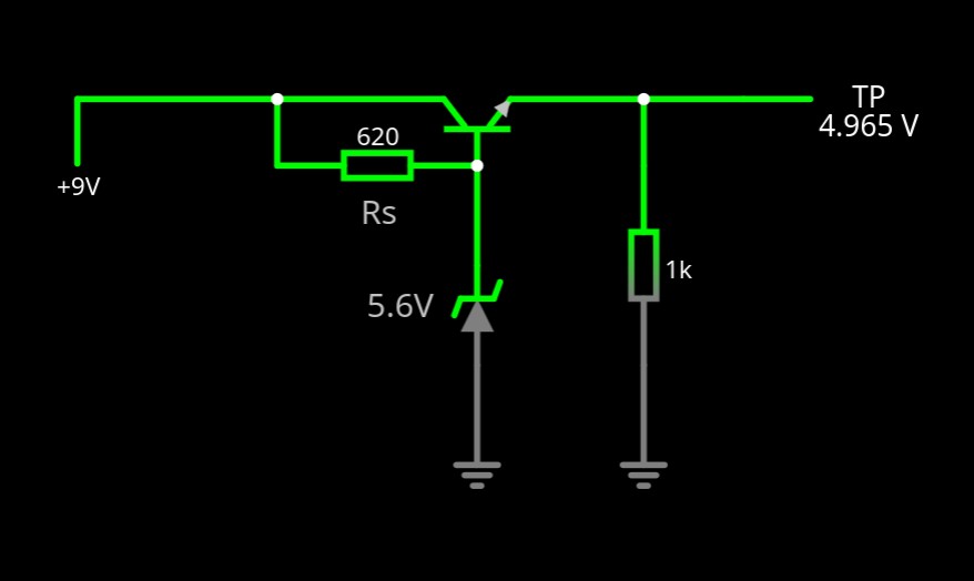
It doesn’t get much simpler that this, well, it does actually if you don’t use a transistor but you won’t get much current delivery.
The key to the circuit is in knowing a number of variables:
- What do you want the load current to be?
- What do you want the output voltage to be?
- What is the likely input voltage going to be?
- What’s the gain (hfe) of the NPN transistor?
How it works.
A Zener diode is used as a voltage reference, in this circuit the voltage is 5.6V. This voltage is supplied to the base of the transistor and the forward volt drop of the base-emitter junction reduces the output at the emitter to (Vz-Vbe) 5.6-0.6=5V.
The input voltage can vary and using Kirchoff’s law there will be a voltage drop across the sense resistor of Vin-Vz and and a current flow. The resistor also provides the bias current for the transistor to ensure it turns on. So, there are two currents to consider in the base circuit.
- Iz. The Zener needs somewhere between 5 and 10mA to maintain the 5.6V reference voltage at the base.
- Ib. This is related to the gain of the transistor and the output current. The base current can be calculated as Ic/hfe. We know hfe and we know the design current from the requirements.
- ib<< iz.
Calculating Rs.
The sense resistor can now be calculated using a simple Ohm’s law calculation:
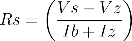
For our simple use case, these are the core requirements.
- ILoad=30mA
- Vs=9V
- Vout=5V
- hfe=100
- Iz=5mA

As this isn’t a preferred value, chose a lower value to ensure sufficient bias is applied to the transistor : 620Ω